Need to find where 2-3 volts loss between full batteries and inside of 2023 T@b 320

I have been trying to resolve this for quite a while. I cannot get it into an RV place before a required upcoming trip, and the local mobile RV mechanic told me I've already done more than he would know how to do. I asked the Nucamp Owners Group FB page, but even Paul Thomas gave up and suggested I ask this group.
I'm going to copy and paste the thread from FB rather than trying to start from scratch to explain what the issue is and what I've done so far.
(Ignore my initial question in the FB post—my T@b has just the battery disconnect switch plus the three inline green fuses.)
Do T@bs (2023 320) have a 12 volt circuit breaker? If so, is it in the box between the front platform box and the camper (the box which the lines from the battery go through to get to the camper)? If not, what is in this box? (Please do not try to tell me circuit breakers are for 120. That's not what I'm talking about. At least some brands of campers have a 12 volt circuit breaker and I'm trying to confirm where mine may be before trying to open that box. And yes, I am aware of the inline green 30 amp fuses that serve, basically, to break circuits. I am not talking about those.)
· The box you are looking at is the "junction box", where the connections between the 7 pin plug wiring, and the battery wiring, enter the trailer before being directed to the WFCO converter for 12V power, or to the trailer running lights. There is no "12V breaker", except for the the battery disconnect switch, or the 30 amp fuse at the battery. Turning off the battery switch will disconnect the 12V power from the battery "before" it reaches the junction box. To completely remove any chance of power at the junction box, you should also disconnect the 7 pin plug from the tow vehicle. What is it exactly are you trying to do? This thread has a discussion of what is inside the junction box, with pictures and drawings of the wiring at the junction box. https://tab-rv.vanillacommunity.com/.../junction-box...
- Reply
thanks. On a quick look at your link, it looks like the box has a bunch of connectors I should check for corrosion or looseness. (I can see that in a sealed box, things shouldn't corrode and hopefully not loosen, but I'm running out of things to check.) I'm trying to find where the lines are losing power between the new fully charged batteries and the camper interior. Two or more volts consistently. I've added an additional ground but that did nothing. And I've done tons of other troubleshooting and replacing, none of which found the problem.
- Reply
This is the link going to the drawing of the wiring inside the junction box. I'm not very skilled at this sort of thing, but the battery wiring from the battery disconnect switch should be easy to trace and check. It is also possible to have some sort of failure of the battery disconnect switch itself, either aging or corrosion. https://tab-rv.vanillacommunity.com/.../comment/128657/...
- Reply
Edited
actually, I was already planning to rewire the disconnect switch as soon as I have time. I replaced it a few months ago when the original died. Since then I’ve replaced and cleans a lot of connectors and such but if that isn’t secure, it could be causing the loss now that everything else seems clean and tight.
- Reply
I finally got to the disconnect switch today. It looked fine (everything tight, no corrosion), but I replaced the new one (a few months old) with the original one. The original had stopped working (no power in the camper) but it's working fine now. And I did get full voltage at each post. I have a new clamp meter but didn't find any amps loss with that today. I have ordered piercing probes but until I have those I don't know of any way to test the million wires under the seat for voltage. I did test every single ring connection at the battery and all show full voltage (I was careful to touch each connector, not the post), and of course the batteries show full voltage. I am at wits end as the probes won't come until to late for my upcoming required trip and I can't find any in local stores. Please suggest what else I can test for the possibly worsening voltage loss. Lately the camper has gone down to around 9.7 when the camper is still well over 12--so around a 3 volt loss.
- Reply
This sort of issue is way over my head, and I wouldn't have any idea of where to start. Are you a Tab Forum member? This is the kind of thing they are pretty good at, and there are plenty of resources that can help dig into the "million wires" you mention of the wiring harness under the seat near the WFCO. (There is info on what each wire is and the function).
Comments
-
Where are you measuring the power in the camper?
What are your symptoms? (fridge not running? lights dimming? CO detector going off?)
I have a clamshell, and there's definitely a voltage drop between the battery and the 12v "cigarette lighter" socket all the way at the back, which I just always assumed was due to wiring length & gauge.San Francisco Bay Area | 2013 CS-S us@gi | 2015 Toyota Tacoma PreRunner Double Cab
0 -
Power at battery via multimeter, battery testers (that also show resistance, state of health, etc.) and Victron app. Power in camper via little plug-in 12 volt device that shows voltage, confirmed by looking at 1-4 lights on camper's battery monitor. Symptoms I already said. Power in camper was 2+ now is usually 3+ volts lower than batteries (2 new 12v batteries). Why a problem—Alde furnace won't kick on when camper reads in the 10s. (or lately, even around 9.7). I keep everything off so just have the small lights that can't be turned off drawing power though I have used the fridge a bit when full sun or when the batteries are on a plug-in battery charger at night. The camper is not in use right now—I am at home trying to resolve the voltage drop before a mandatory trip with the camper quite soon.
You said you always have a voltage drop. Of 3+ volts? And the monitor showing only one light when the batteries are full? That should not be normal.
0 -
You said you always have a voltage drop. Of 3+ volts? And the monitor showing only one light when the batteries are full? That should not be normal.
Sorry if there was some misunderstanding. That's not what I said. I said that I've noticed a voltage drop at the back of the camper. I've never measured it. I noticed that it's enough that my electric cooler (separate from the fridge) doesn't work when I plug it into the 12v socket at the back (but does work when plugged into the trailer interior socket).
FWIW I have opened that box at the front of the trailer and it's simply a junction box. There's nothing in there but posts & wires unless NuCamp changed something and I can't see how adding an inaccessible breaker would be useful when there's already a fuse on that line from the battery. If you search this forum for "junction box" you might be able to find a wiring diagram for the junction box. I know that I had one at some point but I can't find it.
The only 12v breakers I'm aware of are the Gloso breakers in the solar system. I'm pretty sure everything else is just fuses unless someone modified your trailer.There should be one main line going from battery into the converter inside the camper. From there the converter distributes 12v power throughout the camper. Have you been able to identify that one wire and test its voltage at the converter?
Have you noticed any weirdness with your exterior trailer lights (brake lights, turn signals)? A short or bad connection in one of those lines from the box to the light can cause mayhem. I once put a whole new wiring harness in a tow vehicle before I figured out that the problem was the boat trailer lights. Doh!
San Francisco Bay Area | 2013 CS-S us@gi | 2015 Toyota Tacoma PreRunner Double Cab
2 -
The way to track down voltage drop is with a voltmeter (doh ! 😀 ) but not by measuring voltage to ground but by measuring the actual voltage drop in the wiring section by section. E.g. you start at the battery and trace the wire to the first connection point. Measure voltage between those two points, it should read a very low voltage, ideally around 0.2 or less. The actual value depends on how long the wire run is and how much current is flowing through the wire. Do this section by section, you may need a piece of wire to reach between the test points if they are far apart. Note that this needs to be done for both the positive as well as the negative side (it's pretty common on older cars to have ground issues from rust).
1 -
San Francisco Bay Area | 2013 CS-S us@gi | 2015 Toyota Tacoma PreRunner Double Cab
0 -
Several white wires run between the camper and the batteries but I cannot figure out which is what. How do I find the main line you referred to?
I haven't noticed any light weirdness, but I really don't know what they do except when I test them before a trip then look at the side ones while driving when it's dark enough to see them.
0 -
Interesting. That is new to me. I see what you're saying (I believe), but how do I test what I cannot see or reach where the lines all go into and come out of the camper? Or aren't accessible (e.g., to lights, fridge, etc.)?
0 -
You don't have to test every wire, just between the battery and the "power center" a.k.a. fuse box because clearly anything connected there has low voltage issues (Alde, voltage display gizmo).
Actually it just occurred to me that I didn't ask the most important question: Do you have full 12V when the trailer is plugged into 120V ? If so it narrows the problem to the connection from the battery to the "power center".
1 -
Great question! I've never plugged this camper into house power. I'll run some 120 tomorrow. It may be via an EcoFlow power pack, but 120 is 120 so that should work as well as an extension cord. I'll let you know.
0 -
I haven’t seen this mentioned yet but as an aside have you considered the electric brakes? The brakes are powered when the battery switch is on. Probably not the issue but could be.
2023 T@B 320s Boondock, 2013 Toyota Tacoma TRD 4x4 2016 Toyota Tundra 1794 4x4
John, Northern California0 -
How do you suggest i test this?
0 -
The trailer wheels would be locked up. Typically there's also a slight humming noise from the brakes, and the battery gets drawn down pretty quickly. It happens when the breakaway switch at the tongue gets pulled.
Seems unlikely to be the problem though because you would read lower voltage at the battery.
1 -
No problem with the brakes last time I towed the camper.
0 -
Sorry I wasn't precise: The wheels would be locked up with the trailer just sitting, not connected to a tow vehicle. The breakaway switch would apply the brakes at full force.
0 -
0
-
Two separate topics related to voltage issue:
- I decided to test resistance, as I replaced all the ring and Wago connectors at the battery, but that requires accessing two ends of a wire and the ring connectors either go to a Wago or go into the camper (i.e., disappear). Is there a way I can measure resistance of those wires?
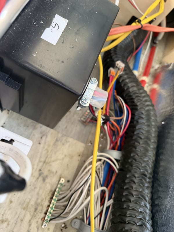
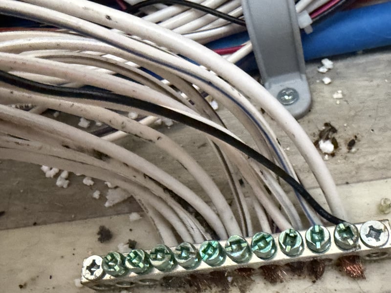
- More importantly, I have a new theory but need feedback. Behind the converter, about 1/2 dozen wires go into the DC side (I'm ignoring all DC lines). Right most is a slightly thick white one that goes to the left end of the terminal block. At the right end of the terminal is another similar white wire that's coming from the wall of the camper so I assume from the battery. I am betting these two are the main wires between the battery and converter. So first question is is that likely correct? I turned on the Alde furnace (sun is shining and the camper shows 11.0 volts which allows the Alde to work) and got .8 to 1. something amps on the right (incoming from battery) and only around .3 or so on the left one (into the converter). If I'm right about the wires, this is showing amperage drop. I can't figure how to test voltage until my piercing probes arrive. That all said, I think the few wires on the left side of the terminal block look awfully gunky. I am thinking I'll unscrew the left-most one, pull the wire and if it is corroded or otherwise gunky, cut, strip, and reinsert it. But I'd really like feedback from more experienced people before I mess around with the terminal block wires.
If I can figure how to post photos here, I'll post one or a few I just took in a bit.
- \
0 -
A lot of good stuff so far in this thread, also some confusion on measurements, methods, etc.
Consider stepping back and documenting or measuring with reference to a single schematic/wiring diagram; for example the one in the attached PDF.
Due to the complexity I've placed my suggestions and some reference material in a PDF file as that was easier to create/edit than attempting to so in the thread text.
'18 320 S, pitched axle, 3020HE; PNW based
TV: '17 Colorado V6 Z71 4x4, Tow Package, GM Brake Controller
TV: '25 Canyon AT4
Adventures: 50 Nights: 415 Towing Miles 50,6501 -
- As I mentioned in my initial response you can use a piece of insulated wire to extend the lead from your multimeter. Does not need to be anything special, voltage/resistance measurement does not use high current.
- What you're looking at is the bus bar where all the negative side connections come together. One of the fatter wires goes into the power center, the other forward towards the battery. The positive side is distributed in the power center via fuses. The fat red cable is the power feed for the power center. It goes forward towards the battery switch and ultimately the battery.
You're sort of on the right track but you use voltage, resistance, current (amperage) seemingly interchangeable. You do not want to try and measure amperage, it doesn't yield any clues. Voltage drop and resistance are basically the same thing, in resistance mode the meter supplies a small current and measures the voltage drop. The reason I prefer to measure voltage drop directly is that voltage drop is proportional to current, the small current from the meter might not be impeded much by a bad connection but the higher current from running lights etc. will cause a larger voltage drop.
If you indeed can measure a sizable voltage drop between the different wires on the distribution block then clean/tighten all the connections.
0 -
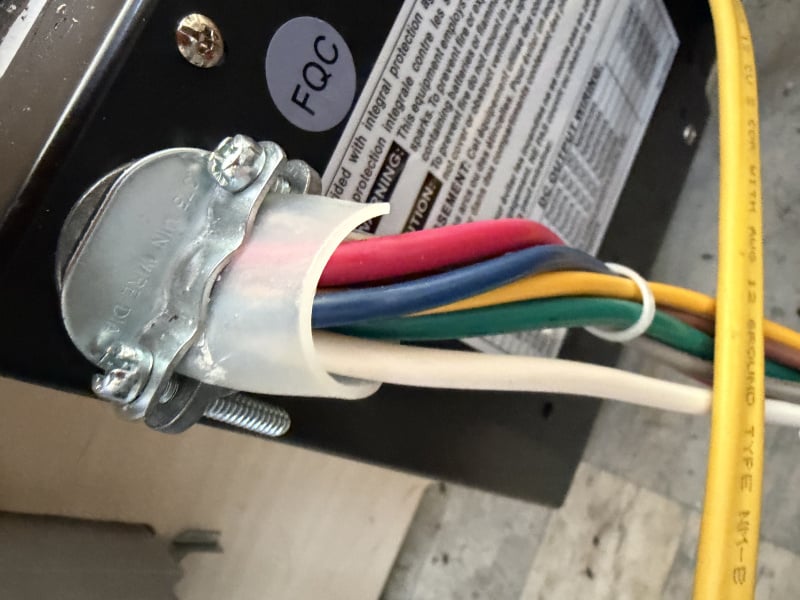
Update—no changes after I cleaned that wire (it wasn't bad). Two questions now. Should I unscrew the holder to the lines in the last photo above to check the end of the white wire? Since I have some power—just not enough—I don't want to mess things up so I have no power.
I then decided to focus (again) on the battery switch. I did continuity testing on both the original and the newer one and both test fine. I put the new one back in. I see 12.8 volts on each side. But with the fridge running I see 2.6 amps on one wire (to/from the switch) and 3.4 on the other. (The actual #s vary as the fridge runs of course, but that's one example of the differences.) Shouldn't amperage be the same both sides of the switch? I am wondering if I should just cut and replace both ring connectors to the switch though both look clean and tight. I'm still trying to find a way to test all the ring connectors when I can only access one end (the ring end) of those wires.
Any thoughts on the battery switch? And whether I should mess with the white line into the converter?
0 -
No, I know full well voltage, etc. all are different. I measure amperage because it's simple to do with the clamp meter. I want to measure voltage. Or perhaps voltage drop as you say. Even with a wire (I do have a 6-7 foot piece of coated 10 AWG wire) I'm not clear where to put that second probe. Starting in the battery box, I can put one probe on any of the ring connectors (or the battery posts). Those lines all "disappear" into the junction box then the camper (I assume). So where do I test?
At the battery switch (which I have the back off of so I can reach the posts and connectors), I can put one probe on the posts or the connectors and another on the camper as a ground, but the red wires from the switch disappear into the camper so I don't see any drop I can test there.
The third area is under the seat, behind the converter. What should I test there, with the zillion wires into the bus, about 6 into the converter? I know to ignore the lines to/from the Victron as solar is working fine. I can see how there I might want to use the separate wire to get to the metal at the entrance I can use as a ground.
0 -
Re this from Grumpy_G: "If you indeed can measure a sizable voltage drop between the different wires on the distribution block then clean/tighten all the connections."
I already did check to ensure all the connections are tight and brushed away loose stuff around there. To test all those wires do I need to put the positive on the first exposed wire (coming out of the bus), with the negative to a ground by the camper door with the long wire? Then do the same for the second? Then the third? And all the rest?
I'm not quite envisioning how I do that—hold one probe on the bus wires, then what—hold the loose wire to the negative probe but also have it securely touching the ground flooring? Maybe tape that down?
0 -
IMPORTANT! Re Grumpy_G's question "Actually it just occurred to me that I didn't ask the most important question: Do you have full 12V when the trailer is plugged into 120V ? If so it narrows the problem to the connection from the battery to the "power center".:
I just plugged it in (probably for the first time ever). I did connect the heavy RV cord to a standard medium weight outdoor extension cord, but since nothing in the camper is turned on, I figure that's OK.
Well… the voltage inside the camper did NOT change at all. It's at 10.8 at the moment.
So the answer to your question is NO!
Does that mean my converter has gone bad?
What else do I need to test?
And if it needs replacing, can I do that or do I need to make an RV shop appointment?
0 -
Oops—further checking.
YES, 120 v is working. I plugged a 120v lamp into an outlet in the camper and it turned on just fine. The battery reads 13.6 or so without 120 plugged in, 13.7 or 13.8 with 120 plugged in. But the batteries are full so it's not surprising the voltage didn't go up, I'd say.
0 -
So I think I'm back to thinking a connector, most likely a ring connector at the batteries or disconnect switch is bad. I really need to figure how to test those specifically. I have looked at them all (and earlier replaced every single ring and Wago at the batteries) and they look fine, but I know the connectors themselves can go bad, e.g., get bent and the like.
If it's not one of those, then there may well be a break in a line, but I really think I need to confirm ALL the ring connectors are working perfectly. That means at the batteries and at the disconnect switch. (Also all the Wagos, but I've looked at all of them and all the wires are shiny, tabs are down tight, and wires are all the way in.)
0 -
Here's another thought. Two red wires go to/from the battery switch but I have no idea which is which. Does it make a difference which one goes on which post in the switch? A disconnect switch simply makes or breaks the connection so I'm thinking it shouldn't matter. I also think I've tried swapping them on the posts already, but if there is a specific order for these two wires, let me know and I'll swap those once more.
0 -
I appreciate your comments and charts but it's all a bit too complex, I fear. I have a regular multimeter, a clamp meter, and several battery testing tools (that show the usual but also SOH and a few other things a multimeter doesn't show). I need some pretty specific guidance how to use those to test whatever I need to test. (I of course know how the multimeter and clamp meter work, how to get to the various settings such as voltage, amperage, resistance, continuity, but need to know where to put the probes specifically for any testing you suggest.)
As I see it, the problem may well be one of the ring connectors (which I've had issues with and replaced in the past on this and another camper) at the batteries or the disconnect switch. Or may be something else of course. The disconnect switch has continuity. The batteries are fully charged (and pretty much brand new and definitely are holding a charge as they should). The converter seems OK (per Grumpy_G's suggestion), that is 120v does work in the camper when a house cord is plugged in.
Are you suggesting (among other things) I should pull each fuse one at a time? I did pull the fridge fuse a few days ago but found no voltage change. When I pull each fuse, other than looking at my plug-in 12 volt meter, what should I check with the multimeter, and HOW? (I'll go through your comments again once I post this.)
0 -
Re your WFCO diagram—I just checked mine again. The front only has a handful of 120v breakers and seven DC fuses (plus a fan output). Nothing else, so I don't see anything that looks like your WFCO DC Fuse Panel diagram.
0 -
@kimch said . . . Are you suggesting (among other things) I should pull each fuse one at a time?
. . . When I pulleachfuse[s], other than looking at my plug-in 12 volt meter, what should I check with the multimeter, and HOW?If this was my trailer, would do:
- Disconnect all Positive Terminal Wires at the Battery.
- Using multi-meter measure voltage between POS and NEG, record for reference.
- Reconnect the Battery Positive Wires One at a Time . . . one of them and only one of them goes to the WFCO Power Center.
- One is most likely the solar controller Bat+
- Another is most likely the Current Shunt Logic Bat+
- Final is wire into trailer; WFCO DC Panel. Your Monitor Panel LEDs will function when this wire is connected. For rest of this test have only 'that' wire connected.
- With Battery Switch Off; Remove all fuses EXCEPT the very bottom two (battery and reverse polarity).
- This will isolate all the trailer loads from the DC panel.
- Reference the Meter Connections Figure in the PDF;
- Measure voltage with your volt-meter between DC Fuse Panel Point B and the ground buss bar (all the white wires location). Record Voltage.
- Compare Battery to Point B:
- 2 or 3 V lower voltage at Point B then problem is most likely in the Cut-Off Switch or Junction Box connections you have been focused on.
- Nearly the same, problem is not wiring from battery to cabin.
- One of the DC Load circuits has an issue or
- Plug-in meter or the socket could have issues. Ideally all measurements should be completed with the same meter. However, the Alde is reporting a lower Voltage as well. so plug-in may be fine.
Also suggest you completely ignore the Monitor Panel LED reading, beyond does something light, as that style Monitor is trash and reads "fair values" when the battery is near dead.
If Step 5 yields (b) nearly the same adn the voltage value is sane [ 12.3V or more ]. Then plug fuses back in One-by-one to see if it is possible to isolate 'the voltage drop problem' to one circuit. You will be repeating the Point B measurement looking for the connected fuse that causes a voltage drop.
'18 320 S, pitched axle, 3020HE; PNW based
TV: '17 Colorado V6 Z71 4x4, Tow Package, GM Brake Controller
TV: '25 Canyon AT4
Adventures: 50 Nights: 415 Towing Miles 50,6500 - Disconnect all Positive Terminal Wires at the Battery.
-
MuttonChops, can you please expand on/clarify these two steps?
"Measure DC Fuse Panel Battery (to Ground) with all Load Fuses [accept battery fuses] removed.
Install Load Fuses one-by-one and only one at a time Does DC Panel Voltage Show the 2-3 volt drop (use Battery switch to power off when handling fuses)'
"Measure DC Fuse…" I don't know what you mean. Remove all the fuses (including the converter one, which cuts all battery power to the camper?), then what—retest voltage at the batteries?
"Install… again, should I leave the converter fuse in through all this or pull it as well? It sounds like you're assuming when I pull them all (except the converter one?) the voltage in the camper on my little meter and on the Nucamp monitor will go up, correct? What if it doesn't?
And on this one "Use Battery…" are you saying to turn the battery switch off and on for each fuse? Off before I pull them, then on and again off after each fuse? Asking because an RV dealer warned me switching that on and off too often can cause the switch to go bad.
0


Categories
- All Categories
- 12 Cirrus Truck Campers
- 128 Dutchman and Vintage TaB Archives
- 3 Forum Rules
- 3 nüCamp & Forum Contacts
- 969 Air Conditioning & Refrigeration
- 2.7K Battery/Electrical & Solar
- 1.2K Camping & Travel
- 145 Events & News
- 220 Factory Comments
- 28 "FOR SALE" - New/Used Trailers
- 15 “FOR SALE" - Camping & Trailer Gear
- 2.4K Heating/Plumbing & Winterizing
- 138 Help - Computer & System
- 925 Introductions
- 408 Looking to purchase a trailer?
- 2.2K Modifications & Upgrades
- 1.4K Products and Accessories
- 425 Service/Maintenance & Recall Notices
- 37 Solo Travelers Hints & Tips
- 1 T@G Forum
- 78 Teardrop Groups & Links
- 78 Testimonials
- 922 Tips & Tricks
- 1.5K Trailer & Towing
- 27 Owners Manuals/PDF Files/Videos & Resources
- 56 üCamp Rally - News & Information