Options

SeeLevel II upgrade, Install instructions

Pop-T@BPop-T@B Member Posts: 199
The SeeLevel II kit was $210.00 with shipping. You will get the 709-P3 monitor, 3-710JS senders and a wiring pig tail. You will need extra wire to run the ground wire and the wire down the wall to the senders on the tanks.

This is how I started, I first removed the fuse for the pump and the old pump switch and disconnected the wires, I then laid out and cut the hole for the Monitor. Cutting the hole was tricky, there is a bundle of wires behind the wall. You need to make sure to keep them out of the way when you are cutting the hole. I carefully drilled holes in the corners of the layout lines for the monitor, I pushed the wires back and used a pencil to hold the wires out of the way while I cut the hole with a hand saw. I won’t go into details on the complete wiring, if you go to Garnet Instruments website you can download the complete install manual


Pencil is used above to hold bundled wires inside wall safely to one side while cutting hole.


Use test light to find "12 volt hot wire" and mark the hot wire with a felt tip marking pen.

Water Pump Switch Information

I will cover one thing, they do not give any information on how to wire up the pump switch and the indicator light for the pump. 

The wires on my old pump switch were both yellow in color. You will need a 12v test light. Hook one end of your test light up to a ground make sure the two wires you took off the old pump switch are not touching, reinstall the pump fuse. Use your test light to find out which wire is the +12v hot lead, mark the wire, I used a red Sharpie marker. The other wire is the feed line to the water pump. I also used this +12v hot wire for the +12v feed to the SeeLevel monitor. 
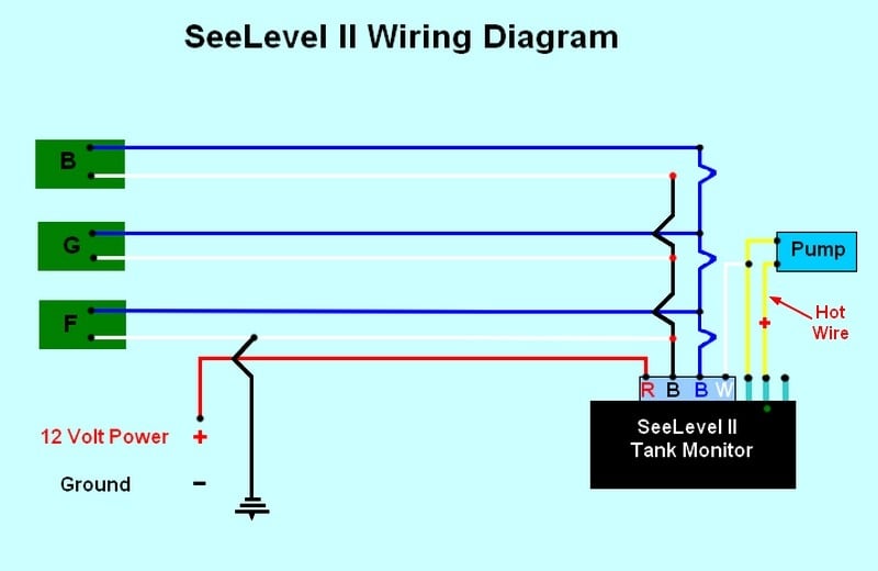
The pump switch on the SeeLevel monitor has three terminals on it, you will use the bottom two, put the +12v hot wire you marked on the bottom terminal, the pump feed wire goes on the middle terminal and so does the white pump indicator wire from the SeeLevel monitor pigtail. This setup will turn the pump and indicator light on when the switch is up. Remove the pump fuse to finish the rest of the wiring.  

SeeLevel II Installation Info - Fresh & Gray Water Tank Monitor Install/Wiring

Now back to the install...   Follow the instruction in the manual on how the mounting, placement, and cutting 
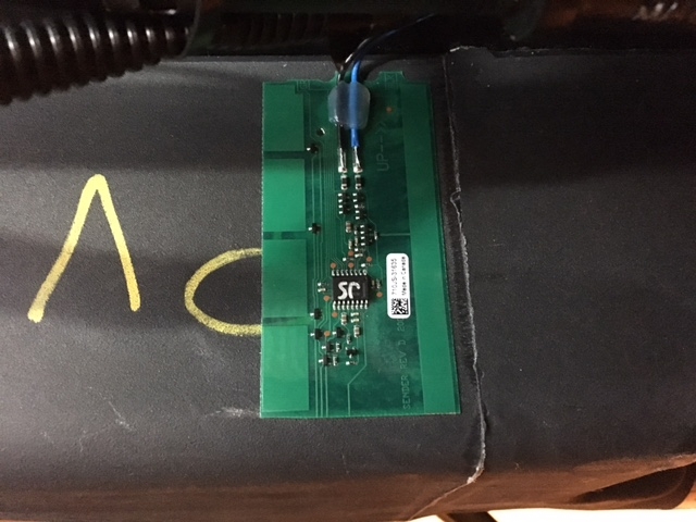
of the senders for each tank. I will tell you I had to cut both of the senders for the gray and fresh tanks to the 4” minimum length. The gray tank is easy, the fresh tank is hard, the fresh tank is shorter by about 3/8” than the strip, I had to move it up and down to get the placement correct. I ran the wires up thru the floor next to the gas line for the stove, then under the cabinet over to the access hole in the side of the lower cabinet under the sink. This is also were you will find the side of the black tank, it will use a full length sender. It’s not too bad to get to. This is also where I hooked all of the wiring together. Please read the manual for complete details on install, wiring and setup. I tested the accuracy of the senders the fresh is not perfect it is off about 3%, the gray and black seem to be dead on. It was a challenge, it took me almost 5 hours start to finish, a lot of up and down under the T@B, all in all it was worth it and I am happy with the install.


To get the Fresh and gray water tanks, I raised the trailer tongue all the way up.


To get up inside the underbelly of the trailer I removed all of the front metal strip and first piece of the metal strip on each side. 

Then you can just roll the plastic covering down and back out of your way. This will give you just enough room to do what you need to do. 


Comments

  • Options
    jkjennjkjenn Member Posts: 6,391
    Bow saw? Just kidding...I see the bent blade.

    2021 T@b 320 Boondock "Mattie Ross" | 2021 T@b Nights: 239 | Total nights in a T@b 455 | 2022 Jeep Grand Cherokee L Overland | T@b owner since 2014

  • Options
    Pop-T@BPop-T@B Member Posts: 199
    its my old trusty saw, I just can't bare to get a new one.
  • Options
    jkjennjkjenn Member Posts: 6,391
    edited January 2016
    What a fantastic write up and great photos to illustrate! Nice work space, too. I'll be over the next time I have a project. =)

    2021 T@b 320 Boondock "Mattie Ross" | 2021 T@b Nights: 239 | Total nights in a T@b 455 | 2022 Jeep Grand Cherokee L Overland | T@b owner since 2014

  • Options
    Pop-T@BPop-T@B Member Posts: 199
    Come on over! it's about a 4 hour drive from Pittsburgh to my house
  • Options
    Tabaz Tabaz Member Posts: 2,357
    Wow! we went from a January 6th post by John_Kris asking if this retrofit could even be done, to Pop-T@B actually doing it!  Is this forum great, or what?!  Great photos and install tips Pop-T.  Posts like this really help the rest of us understand the complexity of a project and whether we want to undertake it.  "What one man can do, another man can." (Anthony Hopkins to Alec Baldwin in "The Edge.") 
    2016 Outback 320 with a 2010 Ford Expedition.
  • Options
    AustinRoamersAustinRoamers Member Posts: 45
    Thank you for the detailed tutorial. That's why I love this forum! Please let us know how the system works for you.
    Kat & Sam      Austin, TX        2018 T@B 400           "Oh, the Places You'll Go!"
  • Options
    John_and_KrisJohn_and_Kris Member Posts: 302
    PopT@B Great documentation!!!! We will be up next week for you to do it on ours...kidding. Again great work and thanks for sharing.
    John - Kris & our Golden "Blossom"
    South Carolina
    Live simply,Love generously,Care deeply,Speak Kindly,Leave the rest to God
  • Options
    jkjennjkjenn Member Posts: 6,391
    Pop-T@B said:
    Come on over! it's about a 4 hour drive from Pittsburgh to my house

    Be careful....a 4 hour drive is nothing to me. =)

    2021 T@b 320 Boondock "Mattie Ross" | 2021 T@b Nights: 239 | Total nights in a T@b 455 | 2022 Jeep Grand Cherokee L Overland | T@b owner since 2014

  • Options
    Pop-T@BPop-T@B Member Posts: 199
    Love to have you over. We have a large yard, we could set up at least 8-12 T@b's in the side yard and have a mini Tearstock this spring :)
  • Options
    Michigan_MikeMichigan_Mike Member Posts: 2,861
    Just found this information buried further back in the threads.   This will be a good discussion for anyone interested to bookmark and save for future reference....  Thanks for taking the time to document your work!  
    Mike - Elmira, Mi / 2019 T@B 400 / 2021 Chevy Silverado LTZ
  • Options
    elmeauxelmeaux Member Posts: 44
    Pop-T@B, do you happen to have picture of how you have the pump wired to the SeeLevel? 

    Mine has the light on when the pump is off and the light goes off when the pump is on. It's been like that since I bought it new last month. I just took a look and mine uses all three terminals with white at the top, then yellow in the middle and red at the bottom. 

    2016 M@x S Sofitel - The T@bahoula
  • Options
    Pop-T@BPop-T@B Member Posts: 199
    elmeaux,   you will need a 12v test light to make sure which one of the wires is the 12v hot lead to the switch. I would guess the red wire is the 12v hot lead and the yellow is the 12v feed to the pump. The white wire should be from the SeeLevel control panel, this is the feed wire for the green light. If the yellow wire is the 12v feed to the pump, it should only have power when the switch is on and the pump is running. once you confirm this, the white wire ( if it is the one from the control panel) needs to be connected to the wire that is the 12v feed ( should be the yellow wire) to the pump when the switch is on. When you are done you will only have wires on two of the terminals. *** short version 12v hot on bottom terminal, pump feed wire and white wire on middle terminal, nothing on top terminal***
  • Options
    elmeauxelmeaux Member Posts: 44
    Thanks. But I don't understand how you are getting two of those blade connectors into the single blade terminal. Those things are pretty tight.

    2016 M@x S Sofitel - The T@bahoula
  • Options
    Pop-T@BPop-T@B Member Posts: 199
    edited January 2016


    This is what I used, it is called a wire tap splice connector. You will need to cut off the terminal end of the white wire and use this splice tap on the 12v pump feed wire.  you can find these at Walmart or any auto parts store. the white wire on my controller did not have a terminal end on it, sorry I did not explain that on the previous post

  • Options
    elmeauxelmeaux Member Posts: 44
    That makes a lot more sense. Thanks! 


    2016 M@x S Sofitel - The T@bahoula
  • Options
    NomadNomad Member Posts: 7,209
    Those are slick little splicers - Used them when I installed the fridge exhaust fan.
  • Options
    SaskTabbySaskTabby Member Posts: 19
    Thanks for the great information!

    I am trying the install on a CS-S and I do not seem to have access to the black water tank.  Did you cut that access hole to the black water tank yourself or if it was already there?  I am considering cutting the hole myself with an oscillating saw but am a little concerned about what I might damage.  Can you comment on the distance between the black water tank and the bathroom wall?  It looks like it is set back a bit.  I believe the cables in your picture are not present in the CS-S as they seem to run up the other interior bathroom wall.  

    Thanks!
  • Options
    Pop-T@BPop-T@B Member Posts: 199

    Sorry for the delay in getting back to you, I was at Tearstock and just got back home today. The access hole for the black water tank was all ready there, I did not need to cut out the hole. I agree there should be enough room, I would just be very careful.

  • Options
    SaskTabbySaskTabby Member Posts: 19
    Thanks for your response.  I hope you had a good time at Tearstock.  The pictures I saw looked like it would have been fun.

    I did create some exploratory holes today and made use of the fibre optic camera.  The tank is far enough away from the wall that there is little chance of puncturing it.  But there are quite a few wires between the tank and the wall, including the speaker wires and some power wires. I will be very careful!
  • Options
    VernaVerna Member Posts: 6,878
    The easiest way to install the SeeLevel is to let Marvin install it!  And this is a wonderful system. 
    Verna, Columbus, IN
    2021 T@B 320S  Boondock “The T@B”
    Towed by a white 2019 Ford F-150 4x4 Supercab, 3.5L V6 Ecoboost “The Truck”
  • Options
    SaskTabbySaskTabby Member Posts: 19
    Believe me Verna, as I have been crawling around on my back underneath the trailer I have often thought about how nice it would be if someone else were doing it! :)
  • Options
    Michigan_MikeMichigan_Mike Member Posts: 2,861
    edited April 2017
    I installed my SeeLevel ll system on my trailer and was commenting to PopT@B about it that it is doable, but on a scale of 1-10 it is probably an 8 as once you delve into it you realize that you've bitten off a tougher than anticipated project and will need to follow through with it as there is no other way around it, or as Verna noted you might want to just let the factory do it for you.  

    The online manual for this system is about 30 pages of information and although it is not complex, it is daunting and the tips given above do help.  The installation does take considerable time and routing the wiring through and into the trailer is the biggest task, then completion of the wiring.  And inasmuch as there really wasn't a good wiring diagram available in the instructions I subsequently ended up with a problem that made the unit operate sporadically and required me to take things apart and find the actual problem which was a wiring problem.  I decided to write up a wiring diagram and post it up in this thread as I believe it will help others out down the road and make this install easier.  

    Some additional pointers for the wiring diagram for the SeeLevel ll system shown above and lessons I learned via this project:

    1. Green Boxes in Diagram Above - The green boxes shown above denote the sending units (the are actually small computer circuits) that are mounted on each tank and marked as B (Black water), G (Gray water) and F (Fresh water).

    2. Water Pump (shown above in blue) - Note that you MUST identify the hot wire and mark it during the installation.  The SL ll monitor will have three electrical points (shown above in blue) behind the pump switch so you will need to connect the two yellow pump wires to the backside of the monitor.  The top terminal IS NOT used and you connect the yellow wires to the lower two terminals.  By doing this the pump light on the monitor will come on when the pump switch is flipped on, giving you a visual that the pump is in use.  If you use the top terminal the pump light stays on all the time, so that is incorrect.

    3.  SL ll Monitor Wiring Harness - The wiring harness on the back side of the monitor plugs into the back terminal of the monitor.  There are four colored wires - Red-Black-Blue-White.

    Red -   12V DC power wire

    Black - Ground wire

    Blue -   Sensor feed wire that communicates to the monitor and provides info.

    White - Used for water pump and ties the water pump into the SeeLevel ll system via the monitor.  

    4.  White Sensor Wire on Sending Unit- The white wire on each sensor unit is a ground wire and these wires are all tied together and attached to the monitor via the black ground wire that is on the SL ll wiring harness.  DO NOT connect the white wires to the white wire on the harness as that is incorrect and will provide an error (open message) message on the monitor.  

    5.  12V DC Power & Ground Wires -  When you install this system you SHOULD also run in a separate red & black wire to provide power for the SL ll monitor.  The trick or task here is to get both wires from the electric converter bench area, under the front of the shower unit (if you have a T@B S unit) and up to the sending unit next to the sink.  This is where all the fun begins and you realize now that you are into it and suddenly wish that you were at the factory in the waiting room and Marvin was the one tackling this project!   =):o

    And DO read the instructions for installing the sensors and wiring correctly.  

    Here is a helpful schematic I put together and will keep you out of trouble if you follow it closely:


    6.  Sensor installation -  the sensors are easy enough to install, but you must clean the surface of the tank prior to peeling off the paper from the sensor units and permanently affixing it to each tank via the adhesive on the sending units.  

    7. Fresh Water Sensor -  Each sensor can be no less than 4" in length and you will find that the fresh water sending unit is 4" long, while the fresh water tank itself is less than 4" in height which creates a dilemma when you are trying to figure out the best means of attaching the sending unit to the fresh water tank.  


    What I did find out after my install (valuable tip here) from the factory and how they install this particular sensor is as follows:  The factory tilts the sending unit side ways or diagonally in a manner where one corner of the sensor touches the bottom edge of the tank and one tip of the sensor meets the top edge as opposed to mounting it upright or in a vertical position.  This allows the sensor to monitor the tank completely and by tilting this sensor slightly, doesn't impact its functionality.  


    The tab ends of the fresh water card DO NOT need to be cut.  The black & gray tank sensor cards come pre-cut and the fresh water card is the only one that will remain un-cut and the system will be able to distinguish and report back on each tank because of this difference.  


    8.  How do I know which sending unit to mount to each tank?  

    Each sending unit will be marked via a "B - G -F" on the sending unit.  You will also notice that a corner on the sending unit has been snipped off with scissors.  The black water sending unit and gray water sending units will have their corner tabs snipped off and the fresh water tank is the only one that does not have the corner tab cut off.  This allows each sensor the ability to segregate itself in the system and communicate to the SL ll monitor and it does work effectively.  By also reading the instructions (via the online manual) you will understand this function in depth.  

    9.  How do I get the sending blue & white unit wires into the trailer?

    As Shawn states in his earlier instructions THERE IS ROOM to run the wires up through the front of the trailer (beneath the Norcold unit) where the propane line enters the trailer.  What I did here was open the door beneath the Norcold unit, drilled a pilot hole through the false floor beneath the sink area and was able to push the wires over to where the black tank sits next to the sink, then up to the monitor next to the sink.  

    I also used a fish tape and was able to fish the red & black wires from the electric converter bench area over to the pump area (behind the shower) and then over to the SL ll monitor next to the sink.  

    Therein lies the challenge and the above information SHOULD come in handy as did Shawn's earlier write-up and a long conversation with him on the phone!  He's a great guy, very giving of his time/talents and expertise and he's a wealth of knowledge/information!   That's what it's all about, helping people out, sharing innovations and in the process, making these trailers more innovative & user friendly!  
    Mike - Elmira, Mi / 2019 T@B 400 / 2021 Chevy Silverado LTZ
  • Options
    SaskTabbySaskTabby Member Posts: 19
    Thanks Michigan_Mike, that is some very good information.  

    Since the CS-S is a little bit different than the other models, here are my CS-S "lessons learned" in case they benefit anyone else:
    1) I am not sure where the factory is mounting it, but I placed the SeeLevel panel above the Alde panel.  I did remove and re-install the TV to make wiring this easier.  Don't worry about bright lights keeping you awake at night as the panel display turns off automatically when you are not using it.

    2) I ordered the 709-P3W model.  I am not currently using the LPG or the pump switch but I wanted to have the option.  In particular, I am considering wiring the pump such that I could turn it on from either the rear kitchen switch or the SeeLevel panel inside (for example, for a roadside pit stop).  However I am going to camp a few more times to help decide whether I should bother.

    3) I cut a hole in the wall against the bathroom under the front cupboard to access the black tank.  I have included a picture below.  Please forgive my hack job.  All will eventually be hidden behind a nice panel.  You'll have to cut this hole blind and it is awkward working inside the cupboard.  I had Initially planned to place the hole closer to the front of the T@B (see the extra cut mark to the lower right of the hole), but you will notice that there are both wires and plywood located there.   Best to avoid both and therefore I would recommend cutting this hole closer to the cupboard door.  Also, there were some speaker wires in this area so be VERY careful when you cut.

    4) I routed the wires from the black sender to the SeeLevel control panel by fishing them from under the converter bench area, around the base of the shower/toilet and to the hole.  

    5) Please see Michigan_Mike's instructions for mounting the fresh water sensor at an angle.  I did not think of this.  Even though I installed the sender at the tall end of the tank, I think a bit of the sender still extended past the bottom of the tank.  Even so, it still seems to work fairly well.  I think when I hit 0% full I was pretty much empty.

    6) I drilled holes through the floor of the trailer under the converter bench area to run the wires for the senders.  I ran dedicated pairs of wires from each sender to this area under the converter bench (i.e. rather than having extra connections under the trailer to save a little wire).

    7) It may have been a complete waste of time, but I bought some very good electrical tape (it was more cloth tape) and taped down the edge of the senders.


  • Options
    Michigan_MikeMichigan_Mike Member Posts: 2,861
    For anyone looking to add-on the SeeLevel ll system the above information was updated today and should be helpful as I added in some additional photos of the freshwater tank sending unit card to show how it is properly mounted as the tank is less than 4" in height.  Mounting the card diagonally solves the card length issue (it does work) and you should temporarily tape it to the tank, fill the freshwater tank up with water and test its function prior to permanently attaching the sending unit to the tank.  You only get one chance with this task after peeling back the paper and fully exposing the adhesive, so ensure the surface is clean and then attach the sending unit as shown above.  

    I was able to register 100% full on the tank and while emptying the water I did see the difference in tank readings.  Interestingly enough when the water level dropped down to about 25% freshwater in tank the pump started struggling to pump water up, so be forewarned prior to showering as you won't have enough water available to take a shower in the S model units.  

    Just sayin!   ;)
    Mike - Elmira, Mi / 2019 T@B 400 / 2021 Chevy Silverado LTZ
  • Options
    PhotomomPhotomom Member Posts: 2,217
    Interestingly enough when the water level dropped down to about 25% freshwater in tank the pump started struggling to pump water up, so be forewarned prior to showering as you won't have enough water available to take a shower in the S model units.  

    Just sayin!   ;)
    I've observed this as well.
    John and Henrietta, Late 2016 T@B S Max in Western New York
  • Options
    kenclunkkenclunk Member Posts: 6
    Photomom said:
    Interestingly enough when the water level dropped down to about 25% freshwater in tank the pump started struggling to pump water up, so be forewarned prior to showering as you won't have enough water available to take a shower in the S model units.  

    Just sayin!   ;)
    I've observed this as well.
    I'm noticing this too, on our new 2017 tab s. 

    So is the consensus that water is completely gone when it hits 25%, or just that the meter is off?

    I'm de-winterizing for the first time and can't seem to get all of the water out of the fresh water tank. Meter says 25% and when I put the pump on I still hear some gurgling. Already opened the fresh water, cold water, and hot water valves. 

    What corner of the tab is the tank at? Is there an angle I could set the tab at to make sure it drains completely?
  • Options
    Michigan_MikeMichigan_Mike Member Posts: 2,861
    edited March 2017
    The water isn't completely out of the freshwater tank, the pump is struggling to pump water up as there is air entering the line.  The tank monitor is doing its job in reading/monitoring the water level in the tank so nothing is wrong there.  

    The freshwater tank sits behind the axle and more to the rear of the trailer.  In order to remove the remaining water you need to lower the front of the trailer down to its lowest point via the trailer jack and open the freshwater valve (mine is just behind the step) and let it empty out as much as possible.  

    You should also buy one of the brass valves that screw into the city water port of your trailer (has a Schrader style bike air valve on it), attach either a bike pump or air compressor (set to about 20# PSI) and blow out the lines to remove excess water as needed.  This may require several attempts to complete this process.

    The lower you can get the front of the trailer down, the easier it will be to remove any remaining/trapped water you have in your freshwater tank.  
    Mike - Elmira, Mi / 2019 T@B 400 / 2021 Chevy Silverado LTZ
  • Options
    jschemeljschemel Member Posts: 79
    In the clamshell the fresh water tank is in rear with kitchen. How does one get all the water out? 
    Jaynie and Larry - Palo Alto, CA - 2015 T@B CS-S - Expedition EL - Nights spent in "T@b Spirit of Holly" 97
    (9/22/19/
Sign In or Register to comment.